Encoding Layers in GKR
At this point, we have all the puzzle pieces needed to describe the GKR protocol -- layered arithmetic circuits, multilinear extensions, and sumcheck. This section talks about how we can tie all of these concepts together to verify claims on the output of an arithmetic circuit.
Grounding Example
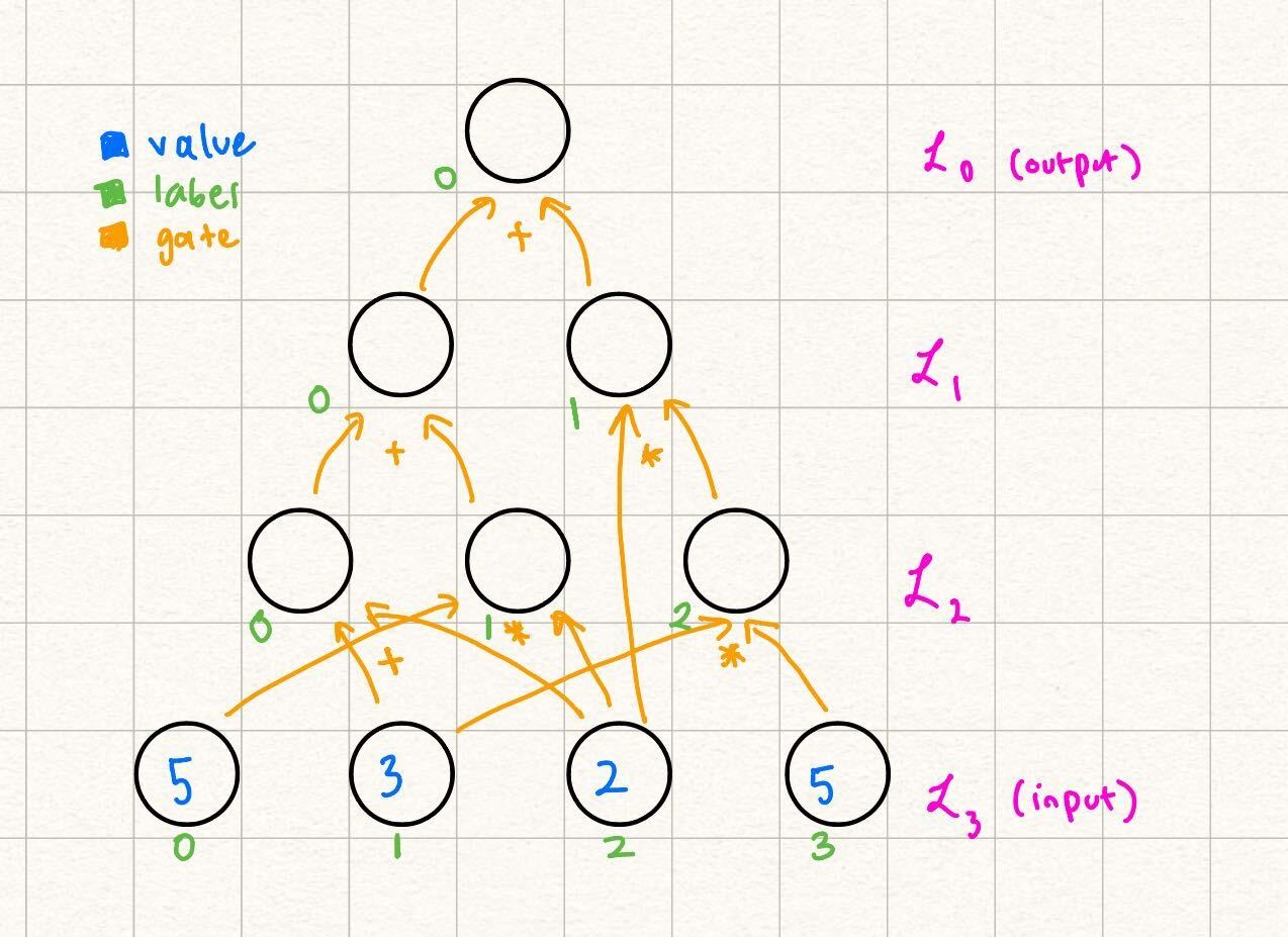
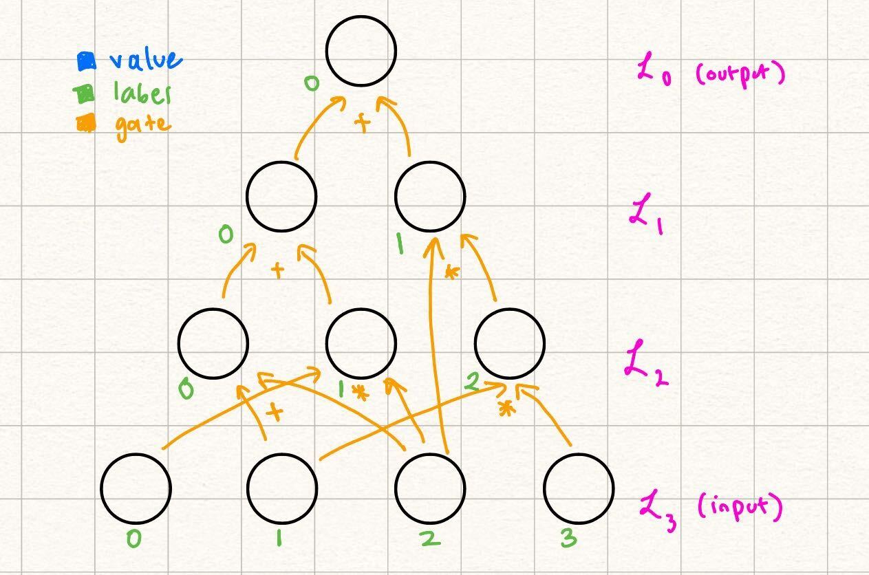
We start with an example layered arithmetic circuit. Throughout this tutorial, we will provide this concrete example while simultaneously providing the generic steps of GKR.
Note some differences from the way this circuit is labeled as opposed to the example in the statement encoding section. Over here, we let the output be a nonzero value for the sake of the example (we explain how to transform any circuit with nonzero output to a circuit with zero output in a future section). Additionally, note that the gate labels start from in each layer, as opposed to the labels being unique throughout the entire circuit in the previous example. Because our gates and are unique per triplet of layers , we can start from in labeling the gates at the start of each layer.
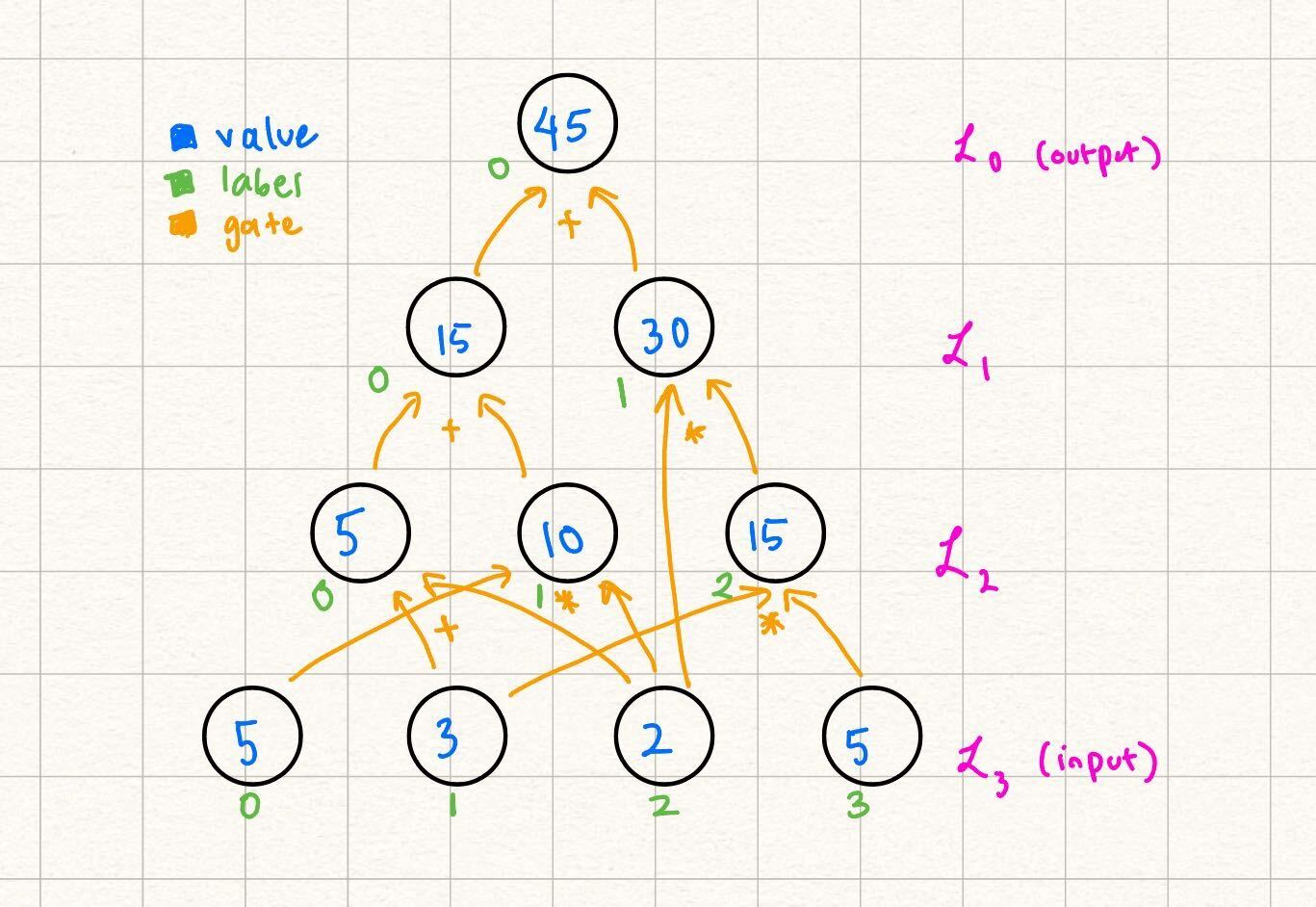
In this example, claims that the output of the following circuit is Note that beyond the values in the input, and the actual structure of the circuit (what we refer to as the circuit description), does not need any more information to verify the output of the circuit by computation:
This is because every node in every layer with can be computed as the result of gates applied to nodes in previous layers.
At a high level, for the rest of this section we focus on encoding layers in two ways: as an MLE of its own, and using its relationship to other layers (via gates). We can equate these two encodings because they are of the same thing (the values in a single layer). With that, we have an equation we can perform a sumcheck over.
Encoding Layer Nodes as an MLE
We start by encoding the input layer in our example, and then show how this extends to the general case. More concretely, we want an MLE such that Although it might not be immediately evident, because we eventually want to invoke the sumcheck protocol, it is useful to consider the inputs as bit-strings rather than integral values.
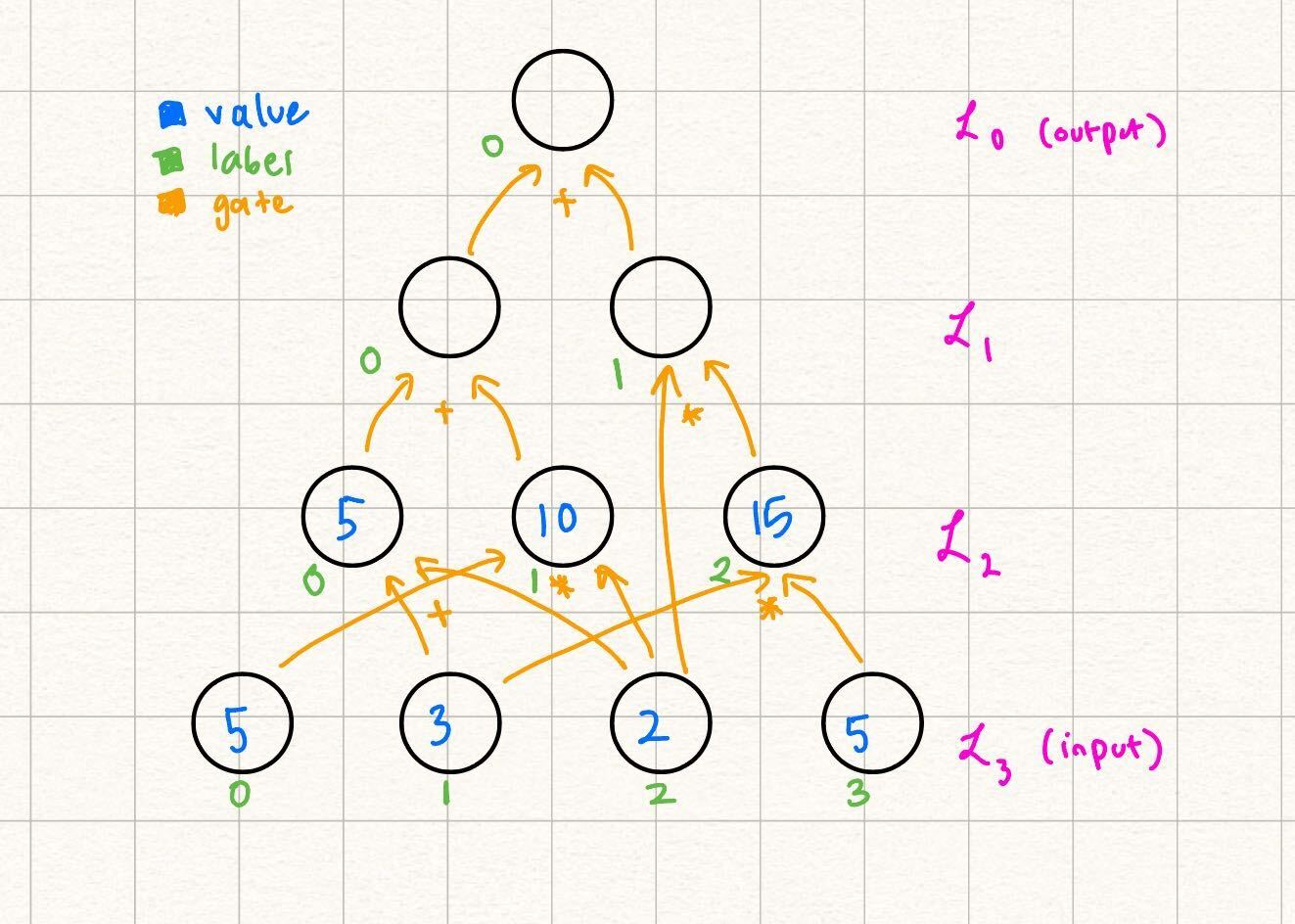
Example
Therefore, for example, we want because and the bit-string represents . Another way of restating our problem statement of encoding the input layer as some MLE is to say "when , output
Here we can leverage the power of the MLE: or in other words: You can independently verify that at each of the node input label values, outputs the correct value.
General
Note that we conveniently defined the node labels to start from and naturally enumerate the nodes in each layer in our definition of above. This allows us to generally extend the function which represents the nodes of layer into the following MLE: where is the number of nodes in layer .
Encoding Layers using their Relationship to other Layers
Another note we made when presenting the above diagram was that the only information that needs to know immediately is the values of the input itself and the structure of the circuit. This is because the values of the future layers are determined by nodes in previous layers and the gates that connect them. Let's formalize this statement below.
Example
In the running example, let's fill in the layer
We were able to fill this in because:
So, while one way to write the MLE representing , as explained in the previous section, is we can also represent it by its relationship to the nodes in Note that in this definition, we still are linear in the variables
General
Now we go over how to write in terms of for Recall the definition of and . For example, in the case of :
If we use the indicator functions and to translate the example above: where are the number of bits needed to represent the node labels of that respective layer. We know that and can be computed using MLEs for and , so we can rewrite the above as: More detail and examples on transforming these indicator gate functions into MLEs are described in the section on canonic GKR.
Using the Equivalence between Layer Encodings
Now we have enough information to show how we can reduce claims on one layer to claims on the output of an MLE encoding a source layer (closer to the circuit input layer) for that layer.
Example
We start with the MLE encoding the output. claims that the output of the circuit is , i.e., . Then, at any random point challenges with, say , because is a constant function, an honest claims that .
Another way, as expressed above to write is as:
Note that while we expicitly write to maintain consistency between earlier examples, in this case, because there is only one output, there are no variables. Therefore, and are constant functions, and their extensions are equal to their value in their first position: and .
and engage in a sumcheck protocol to verify this claim of the sum of a polynomial over the boolean hypercube. Recall that sumcheck requires binding the variables that the sum is over (in this case, ), one by one, with random challenges.
If we follow the sumcheck protocol as is, at the end, is bound to and is bound to . Let's say the prover's final univariate is and the verifier's final challenge is Then, we end with the final claim:
knows the structure of the circuit, so they can compute on their own. Additionally, is publically computable, so computes that on their own as well. Normally, sumcheck would require make a query to an "oracle" to verify the claimed values and .
However, instead we say that "reduces" the claim that to two claims on
Similarly, has a relationship to MLEs in later layers, so the sumcheck on will reduce to claims on these MLEs, eventually propagating to claims on the input layer.
For another example of claim reduction for structured GKR, see this section.
General
In general, GKR works very similarly to the example above. We cover the case where expects the output of the circuit to be . receives a challenge from and claims that the MLE representing still evaluates to over that random point. I.e., claims that Using the encoding of using later layers, reduces its claim on the output of the circuit to evaluations of MLEs representing future layers.
Note that there is an exponential blow-up of claims when reducing claims on one layer to the next. We describe a protocol to aggregate claims (and therefore achieve a one-to-one reduction) in the claims section.
Circuit Description
Throughout this section, we refer to using the description of the circuit in order to evaluate the gates or to understand the layerwise relationships on their own. The circuit description is something agreed upon beforehand with and and visible to both parties -- it is the "shape" of the circuit, which includes how many nodes each layer contains, the number of layers, and which gates connect nodes from layer to layer.
Therefore, the circuit description of our example circuit is this:
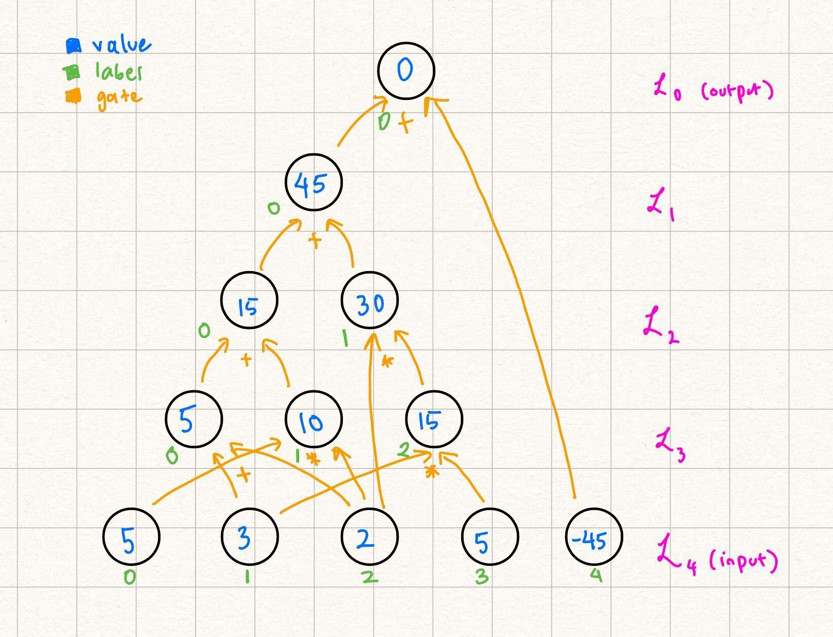
Note: Transforming a Circuit to have Zero Output
In Remainder, expects circuits to have output . This is because certain types of circuits (such as those resulting from LogUp) require the output to specifically be , and needs to specifically verify this fact.
If a circuit does not have output , one way to transform this is to add the negative of the expected output to the input. The last layer of the circuit can be the sum of this expected output, and the actual output of the circuit. This results in a circuit with the output layer evaluating to . We show this transformation applied to our example above: